工研院/蔡華龍 許崇仁 辛伯修 黃貴笠
Different from earlier generation changes, the 5th generation of cellular communications (5G) will not only considerably improve the telecommunication services currently offered to the end users, but it will enable the support of evolved services tailored for other industries and humankind as such, for instance vehicular safety and transport system efficiency, industrial control, eHealth applications, etc. Accordingly, 5G sidelink have been considered to be one of native components in 5G in order to provide direct inter-device communications. To take advantage of such direct communications, techniques for control signaling improvement are proposed, including group based RACH access, multi-connectivity based service continuity management, and context aware group mobility management. In addition, to improve 5G sidelink data communication efficiency, techniques for 5G proximity-based service in ultra-dense networks have been evolved such as 5G proximity-based service for IoT, cooperative transmission and content caching. Simulation evaluation has been made to highlight the benefits of these techniques.
1. Introduction
5G sidelink communication refers to “direct mode” or “locally routed” path for communication between UEs. Direct mode here refers to scenarios where devices participating in 5G sidelink communication are at the same level of network hierarchy and are located in proximity to each other. As a result, use cases such as dense urban information society, massive distribution of internet of things (IoT), and connected cars are envisioned in 5G. In order to support the new possibilities, 5G sidelink is expected to play an important role as an integral component of 5G system.
Going forward into 5G era, 5G sidelink functionalities are expected to be natively supported into the control plane protocol stacks of novel radio access technology, rather than as add-on functions, from device as well as network perspective. Thus requiring several considerations and also imposing challenges from control plane design perspective e.g. to support efficient and optimal resource management and channel access, unified addressing, cooperative communication, network offloading and multi-RAT Mobility Management.
1.1 5G Proximity-based Service
The “Dense urban information society” use case in Figure 1 (a) is concerned with provisioning of ubiquitous connectivity for humans and machines in a dense urban area, including indoor environments. To provide new 5G services, we consider not only the communications between humans and networks, but also direct communications between humans and devices or between both. That is so-called 5G sidelink communication, which is expected in 5G era to provide 5G proximity-based service for traffic offloading and short-cutting. [2].
5G proximity-based service is also foreseen in IoT application area, as shown in Figure 1 (b). The importance of this area will grow together with the massive deployment of IoT devices featuring low cost and of low energy consumption, such as sensors of humidity, wind meters, etc. In order to increase environmental awareness and better user experience, and to get the maximum of information from these devices, there is a need for these devices to be able to directly communicate with other devices.
The use of 5G proximity-based services is also applicable at higher user mobility, e.g. while driving cars (as shown Figure 1 (c)). One can expect that the connected car provides a safe and efficient journey via the 5G sidelink communication to its surrounding. The communication is expected to provide applications such as car collision avoidance, traffic jam avoidance and fuel consumption optimization.
![Fig. 1 Use cases concerned with 5G proximity-based service [1]](https://ictjournal.itri.org.tw/files/file_pool/1/0M266374767506787280/Thumbnail%20%281%29.jpg) Fig. 1 Use cases concerned with 5G proximity-based service [1]
Fig. 1 Use cases concerned with 5G proximity-based service [1]1.2 5G Sidelnk Techniques and Techniques for 5G Proximity-based Service
In order to support several new possibilities envisioned in 5G, 5G sidelink is expected to play an important role as an integral component of 5G system. Going forward into the 5G era, 5G sidelink functionalities are expected to be natively supported into the control protocol stacks of novel RAT, rather than as add-on functions, from device as well as network perspective. This requires addressing several challenges described as follows.
Control Signaling Design for 5G Proximity-based Service
The first challenge is how to enable control signaling between directly communicating devices (e.g. ACK / NACK, CQI (channel quality indicator), feedback etc.); in particular, if this is expected to build upon the same control channels as designed for cellular communications. If for instance there are certain signals foreseen for uplink control signaling, and others for downlink control signaling, then if the uplink control signals are reused for the control signaling between 5G proximity device pairs, a device can only transmit uplink control signals or receive these from another device, but not both at the same time. Solutions are here to either again apply a muting pattern to the control signals, as in the case of channel sounding, or to relay control signals via an infrastructure node.
5G Proximity-based Service in Ultra-dense Networks
5G sidelink communication in ultra-dense networks can be either very efficient or with severe interference, depending significantly how devices in proximity communicate with each other. One can observe advantages of 5G sidelink. That is, 5G sidelink relays can facilitate the transmission between a cellular user and its base-station to improve spectrum efficiency. In addition, 5G sidelink communication in a group of devices in proximity can be efficient if the communication is conducted cooperatively. In contrast, without a proper cooperation, the communications in the group may experience severe interference.
2. Control Signaling Design for 5G proximity-based service
2.1 Group Based RACH Access
As the deployment of a massive number of IoT devices is expected in order to support dense urban area, it brings new challenges to the 5G RAN design with respect to random access of a large number of devices. Unavoidably, this problem should be addressed in 5G. As a result, group-based solutions have been proposed to tackle this problem. In general, a device in a group is selected to be the group head, where devices in the group communicate with each other via 5G sidelink. Through a group-based random access, transmissions in the group can be aggregated. To be specific, when group members have to transmit, only the group head, on behave of the group, proceeds in random access using one of the 64 preambles, which potentially reduces the number of collisions in random access process.
As depicted in Figure 2, without introducing the group-based concept, collisions happen frequently, whereas with the group-based adopted, devices transmit data in different transmission opportunities based on the coordination of the group heads. As a result, fewer collisions occur.
![Fig. 2 Schematic representation of the group based group-based RACH access [4]](https://ictjournal.itri.org.tw/files/file_pool/1/0M266375539963383289/Thumbnail%20%2811%29.jpg) Fig. 2 Schematic representation of the group based group-based RACH access [4]
Fig. 2 Schematic representation of the group based group-based RACH access [4]2.2 Multi-connectivity Based Service Continuity Management
Mobility management is one of the key components of 5G sidelink. Follow-up from [4], 5G sidelink mobility management concept are further elaborated and also evaluated here. The number of 5G sidelink/V2V devices participating and/or part of a particular group can be vary depending on the particular application scenario. For example, a platoon (of vehicles) might consist of a leader and several followers, whereas an IoT group might have significantly more communicating devices than a platoon. In the simple scenario of 5G sidelink communication, a group consists of two devices with a transmitting UE and a receiving UE. The mobility issue arises when such moving group of UEs reaches the cell edge and group members may or may not fully satisfy handover condition simultaneously and thus may not handover to the target eNB simultaneously. The current mobility scheme does not specify the procedures to handover a 5G sidelink/V2V devices in a particular group simultaneously. Besides, 5G sidelink communication uses radio resources allocated by the source eNB for a particular 5G sidelink UE-pair or group. Thus, the established 5G sidelink and/or V2V link within the group or between a pair of 5G sidelink devices would be interrupted, which leads to packet loss. Moreover, each UE in the 5G sidelink and/or V2V is likely to be handed over to the target cell in an individual fashion, which leads to extra signaling overhead.
Therefore, considering a mobility management framework which jointly tackles the mobility management of a 5G sidelink pair is required to reduce possible 5G sidelink communication disruption time due to handover. Precisely, enabling two devices to jointly select and switch to the same target base-station at the same time is expected to control the disruption impact of an active 5G sidelink communication to a lower level. We compare the proposed multi-connectivity based service continuity management (MSCM) method mentioned above with the legacy method. The legacy method is the one currently specified in 3GPP LTE or LTE-A network [5], whereas MSCM is a joint mobility management method. We assume that the interruption time that device experiences during handover in either of the methods follows an identical handover delay probability distribution, which thus causes 5G sidelink communication disruption. Specifically, the handover delay (i.e., interruption time) is defined to be a gamma distribution which is a proper probability distribution to simulate the delay of a series of signaling exchanges of a handover [6]. As defined in [7], the reliability accounts for the percentage of packets properly received within the given maximum E2E latency (OTT or RTT depending on the service). To evaluate the performance of MSCM, Voice over Internet Protocol (VoIP) packet delivery based on G.729 [8] for 5G sidelink transmission is simulated. In addition, the maximum E2E latency (i.e. from 5G sidelink sender to 5G sidelink receiver) is set to 20 ms for VoIP packet freshness. The Madrid Grid [9] [10] is used as the simulation environment in which 8 base-stations (pico cells) are deployed along the roads surrounding the park area (see Figure 3 (a)). Precisely, four of them are located at the corners and the other four are at the middle of the four edges.
From the simulation results shown in Figure 3 (b), we observe that the joint mobility management method proposed in [11] and [4] guarantees a better reliability (up to 95%) than the legacy solution does when inter-device distance is smaller than 40 m. This is because the two UEs can jointly hand over to a target base-station to which both measures “acceptable” signal strength. Among the three factors, inter-device distance is the most significant factor that impacts reliability. In contrast, handover delay brings a minor impact to reliability, where it matters only in cases with high device velocity. The impact of device velocity is “method-dependent” and can be more complicated if Doppler effect takes place in very high device velocity situations.
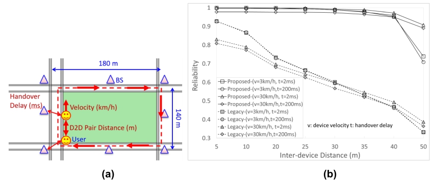 Fig. 3 (a) One pair 5G sidelink simulation environment where the 5G sidelink device pair circulates along the greenfield, (b) Simulation result
2.3 Context Aware Group Mobility Management
One aspect which could benefit from 5G sidelink communication is the location management; where group-based methods are intuitively introduced for handling location management operations in order to minimize the signaling cost. However, such solutions entail drawbacks, including the applicability limitation on cases with cyclic movements or in environments with constraint mobility dynamicity. Therefore, user-oriented Tracking Area List (TAL) has been proposed as a solution to perform location update on behalf of the group. Such design is applicable to already available groups formed for other purposes or undefined ones. Figure 4 shows the TAU process for group location management by exploiting multi connectivity. Only the group head performs TAU in the TAU process whereas all the other devices stop performing location update process once joining the group. The method features on the one hand more often location update for the overall group and on the other hand targeted paging in the cells where the UE is located, thus significantly reducing the user location latency. The cost for the group formation and the maintenance of a group is the tradeoff among the gains of the TAU process. Nevertheless, at least the method reduces significantly the size of paging areas without introducing potential paging misses/failure.
![Fig. 4 TAU update in the group location management by exploiting multi connectivity [12]](https://ictjournal.itri.org.tw/files/file_pool/1/0M266376800686000251/Thumbnail.png) Fig. 4 TAU update in the group location management by exploiting multi connectivity [12]
Fig. 4 TAU update in the group location management by exploiting multi connectivity [12]We compare to two solutions in terms of location management cost. One is based on group location management but the grouping is performed by the core network (e.g., MME) after certain number of joint TAU requests [13], which is thereafter named Group Mobility Management scheme or GMM. The other is an extension of the TAU process with TAL design for increased accuracy, which is named enhanced GMM. To improve accuracy, the devices form a group when the network identifies a stable pattern of that group. To maintain stability of the group, the devices have to perform the periodic TAU.
In the simulation parameter settings are as follows.
|
Parameter
|
value
|
|
Number of Devices in a Group
|
3 to 8 [14]
|
|
Car Flow
|
17800 for 15 minutes [14]
|
|
Cell Reselection Rate
|
30 per UE/hour [15]
|
|
TAU Rate
|
1.2 per UE/hour
|
Figure 5 shows the signaling cost for small (3 group members) and large (8 group members) groups. It can be observed that the enhanced GMM outperforms the GMM when a small number of re-grouping is considered. When the re-grouping number increases to 8 group members, the GMM seems to perform better. However, communications in a big group is tend to be unstable which leads to a higher paging miss. In addition, due to the unstableness, re-grouping then performs frequently to keep the group stable, resulting in an implicit increasing signaling cost.
![Fig. 5 RAN cost for TAU for the three different schemes considering re-groupings for small and larger groups [12]](https://ictjournal.itri.org.tw/files/file_pool/1/0M266377081220989289/Thumbnail%20%281%29.png) Fig. 5 RAN cost for TAU for the three different schemes considering re-groupings for small and larger groups [12]
Fig. 5 RAN cost for TAU for the three different schemes considering re-groupings for small and larger groups [12]3. 5G proximity-based service in Ultra-dense Networks
3.1 5G Proximity-based Service for IoT
IoT devices can be located in the deep indoor placements. To overcome the propagation constraints in IoT communication, the method needs to provide improvements on service availability and battery life of IoT devices. To this end, IoT devices located in cell boarder are selected as relays for relaying data of the other IoT devices. In addition, context information are collected and exploited in order to set up and maintain 5G sidelink pairs.
In this scheme, there are three different transmission modes:
(1) cellular transmission mode, in which the devices upload their reports to base-station with cellular links;
(2) relay transmission mode, in which the devices are configured by network to relay the reports from remote UEs and meanwhile transmit their own reports to base-station;
(3)5G sidelink transmission mode, in which the remote UEs transmit their reports to relays.
In order to adapt to system changes in real time, IoT devices operate periodically in two phases: (1) grouping; (2) transmission mode selection. In order to achieve a high efficiency, 5G sidelink communication should be used when the two devices are in proximity. Moreover, for devices locating near the base-station, 5G sidelink transmission mode is not considered because of relatively low signal propagation losses.
In order to optimize the system performance, channel state information between base-stations and IoT devices and battery level information of IoT devices. Once the base-station collects the list of selected relays in a group, it evaluates energy efficiency in different modes and coordinates 5G sidelink set up between relays and IoT devices in the group if a better energy efficiency is expected in the 5G sidelink communication mode.
Figure 6 shows the cumulative distribution function (CDF) for IoT devices in a number of days. The area of a group is set to be 2500 square meters. In this work, LTE technology is used for modeling radio links, which means if a radio link is with a very low SNR, no data transmission is possible on this link. 15% of IoT devices are in outage of LTE network and cannot be served (referring to the curve with legend “LTE”). The steps shown in the figure is the result of the fixed modulation and coding scheme. In other words, UEs experience different SNR values yet inside the same small range, their spectral efficiency can be same. Therefore, the time to transmit one data packet experienced by different UEs could be the same. The “Distance+CSI based grouping” scheme achieves that 99% of UEs are served by either cellular or 5G sidelink and 75% UEs can meet the 10 years battery life requirement. However, TMS can improve the value to 90%.
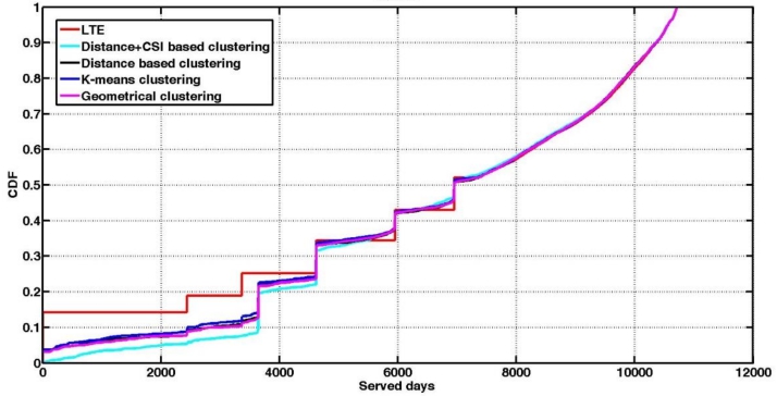 Fig. 6 CDF plot for served days of IoT devices
3.2 Cooperative Transmission
Cooperative 5G sidelink communications where 5G sidelink pairs implement relay functionalities to facilitate transmission between a cellular user and its base-station is a way to improve spectrum efficiency. In such scenarios there is unicast 5G sidelink communication and/or one-to-many/all 5G sidelink communication among pairs of devices over 5G sidelink interface i.e. one of these devices can be source (5G sidelink Transmitter) while other as destination (5G sidelink Receiver). Cooperative communication scheme enables 5G RAN to dynamically allow cooperative 5G sidelink mode selection and communication, at the same time ensure interference mitigation e.g. in case of simultaneous 5G sidelink communication and cellular user to base-station communication over the shared radio resources, etc. To enable cooperative 5G sidelink communications, among others, approaches for cooperative mode selection, relay selection, cooperative transmission and resource allocation are discussed in [4]. In 5G sidelink communication, interference management is one of the key topics for ensuring high spectral efficiency, and various techniques involving MIMO signal processing, power control, and transmission mode selection have been proposed to reduce the interference between the 5G sidelink pair and the cellular user or base-station, especially when multiple 5G sidelink pairs are allowed to share the same channel. A 2-phase cooperative communication mechanism (2CCM) is proposed to further mitigate the interference both among 5G sidelink pairs and between the 5G sidelink transmitters and the cellular system. By allowing cooperation among 5G sidelink transmitters, as illustrated in Figure 7, more 5G sidelink pairs can be allowed to transmit simultaneously in the same and limited spectrum resource, increasing the spatial spectrum utilization of the system.
Through cooperation, transmitting terminals can together form a virtual antenna array to increase their transmit reliability or throughput. However, this typically requires data sharing transmission and coordinative joint transmission among cooperating terminals, which can be costly, especially for long-term resource balancing consideration. Besides, fairness consideration is also important to allow each 5G sidelink pair to achieve at least the same performance as that with no cooperation.
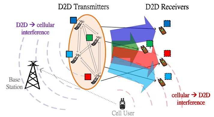 Fig. 7 An illustration of cooperative 5G sidelink transmission
 In order to increase the number of simultaneously communicating 5G sidelink pairs in the same and limited spectrum resource that the system can accommodate and to enhance the spatial spectrum utilization, we consider a two-phase cooperative 5G sidelink transmission method that consists of data sharing transmission in phase 1 and cooperative joint transmission in phase 2. Resource balancing between the two phases is considered in our design.
In the data-sharing phase, each 5G sidelink transmitter utilizes a physical layer multicasting scheme to efficiently transmit its data to all other cooperating 5G sidelink transmitters; and, in the cooperative joint transmission phase, the 5G sidelink transmitters adopt a multi-user block-diagonalization precoding scheme to transmit all 5G sidelink transmitters data jointly to the corresponding 5G sidelink receivers. The rate is limited by the minimum of the two phases, and the sum power over the two phases must satisfy each 5G sidelink transmitters individual long-term power constraint. More importantly, fairness must be ensured in terms of allowing each 5G sidelink pair to achieve at least the same performance as that with no cooperation. When the 5G sidelink system underlays the cellular system, the interference that the 5G sidelink causes on the cellular system must also be limited. These issues are taken into consideration in our design.
Our main objective is to find suitable covariance matrices of the designed pre-coders in phase 1 and phase 2 respectively. This is to maximize the long-term sum utility of the system, subject to long-term individual power and rate-gain constraints as well as a constraint on the interference at the base-station. Here the long-term individual power constraint is used to limit the energy consumption of each device; the long-term rate-gain constraint is used to ensure that each 5G sidelink pair achieves a larger rate through cooperation; and the interference constraint limits the interference that the 5G sidelink transmission may cause on the cellular system. Formulation details of the optimization problem and the simplified implementation method to solve the optimization problem is provided in [12]. Additionally, 5G RAN needs to implement below functionalities in order to enable cooperative 5G sidelink communications among devices:
eNB provides assistance information to select 5G sidelink pairs in a particular cooperative 5G sidelink group, including determining the number of 5G sidelink pairs in the group. Based on the geolocation information of the 5G sidelink pairs, eNB can determine which 5G sidelink pairs can be grouped to perform cooperative 5G sidelink method and inform to these 5G sidelink pairs. Besides, the throughput improvement for the cooperative 5G sidelink method will be saturated when the number of 5G sidelink pairs in the group is large enough. Hence, eNB should limit the number of 5G sidelink pairs in the group based on some information from the 5G sidelink pairs, e.g. the indication of the achievable throughput for the cooperative 5G sidelink group.
- eNB provides assistance information to perform 5G sidelink synchronization for the 5G sidelink pairs selected in the cooperative 5G sidelink group.
- eNB provides assistance information to allocate resources, e.g. channel state information both among 5G sidelink pairs and between the 5G sidelink transmitters and the cellular user to the 5G sidelink transmitters, so as to perform the cooperative 5G sidelink method.
Performance comparisons of average sum throughput between 2CCM, which is a cooperative 5G sidelink transmission method, and the non-cooperative method at different 5G sidelink pair number are evaluated. We consider a scenario, as shown in Figure 8, where the base-station is located at the origin, and a cellular user (CU) is randomly distributed in a circular cell of radius r1 meters. And, 5G sidelink transmitters (DT) are randomly distributed with uniform distribution in a circular area with radius d1 meters, and 5G sidelink receivers (DR) are randomly distributed similarly in a ring with inner and outer radius equal to d2 and d3 meters, respectively.
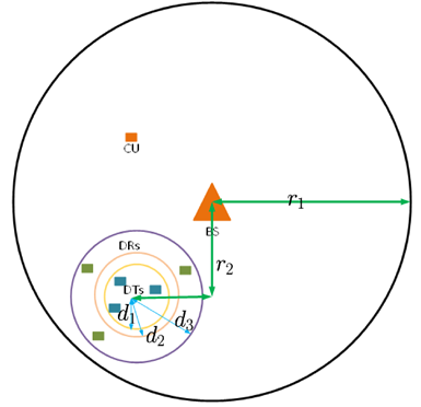 Fig. 8 Illustrations of distributions of 5G sidelink pairs, cellular user and base-station in the simulation
 In Figure 9, we show the average sum rate versus SNR of the individual pairs for the case where d1=1 meter, d2=30 meters, d3=40 meters and r1=300 meter for both the cooperative 5G sidelink transmission method, i.e., 2CCM, and the non-cooperative method. This is the case where the 5G sidelink transmitters are close to each other. The performance of 2CCM is compared with the non-cooperative case. From the simulation results, we can see that the average sum rate increases with the number of 5G sidelink pairs regardless of whether cooperation exists because more 5G sidelink pairs are considered for data transmission. However, the improvement will be saturated when the number of 5G sidelink pairs is large enough. Besides, the average sum rate in the cooperative 5G sidelink transmission method is better than that in non-cooperative method because resource balancing and fairness (rate-gain constraint) are considered in 2CCM.
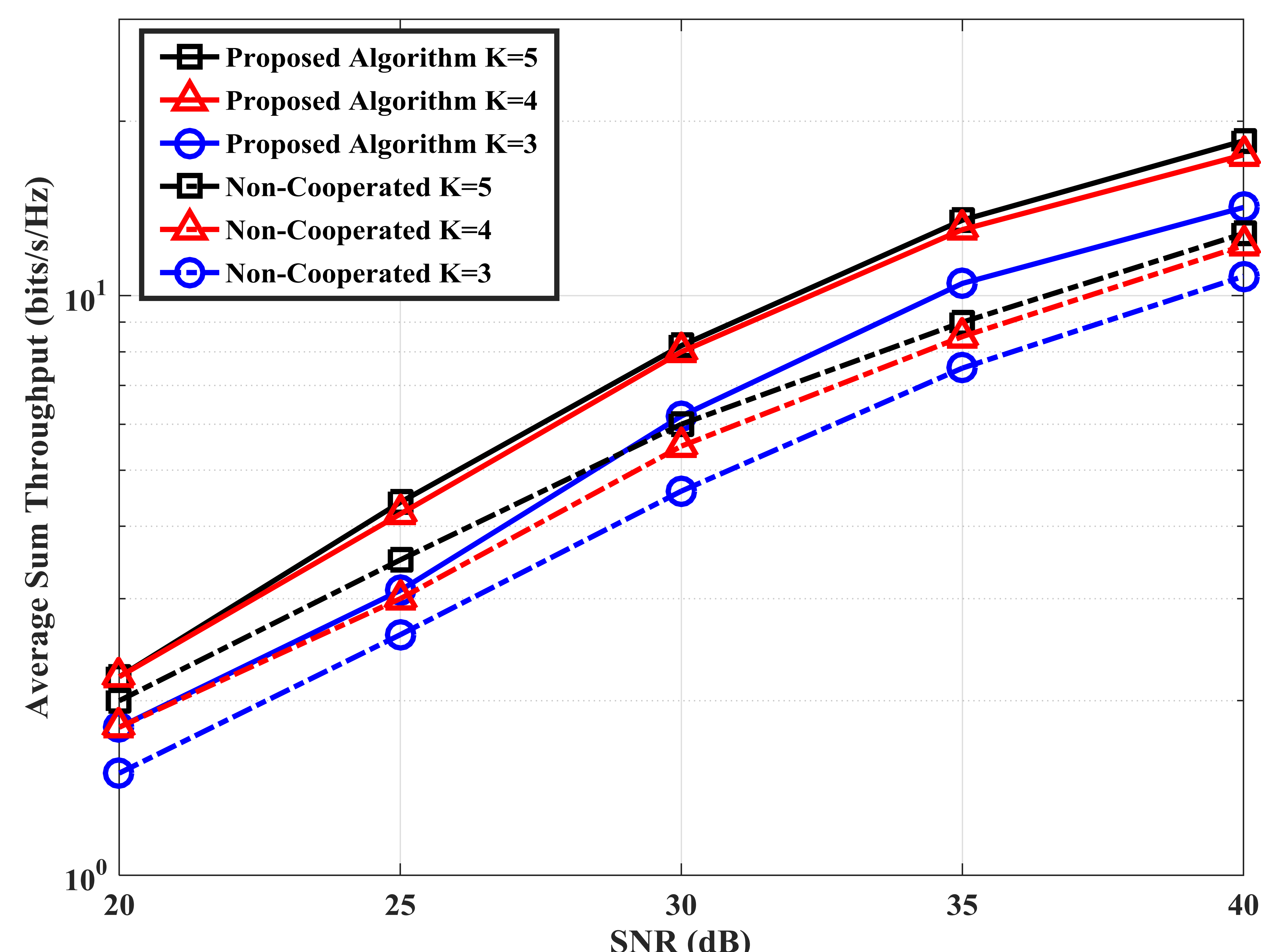 Fig. 9 Performance comparisons
The concept described herein is a cooperative communication concept called Group Transmission (GT). Using GT is a way to implement joint transmission to increase the coverage and user bit rate compared to legacy single UE transmission. The operation of the GT concept is illustrated in Figure 10. On a high level, the first step is to discover potential group members willing to participate in the group. This is done via 5G sidelink signaling between UEs. In this step, one of the UEs is selected as the group coordinator. The next step is to synchronize UEs that are outside network coverage by forwarding information or radio resource management information from group member UEs that are inside coverage and capable of relaying such information from an eNB. Then, when a UE within the group has UL data to transmit, it distributes the data within the group (possibly relaying may be used). In the final step, the data is transmitted jointly by all UEs in the group. Related synchronous control functions details are elaborated in [16].
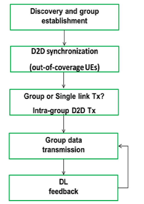
Fig. 10 Group Transmission concept and Operation
3.3 Content Caching
Content caching near the consumer is a way for enhancing QoS, E2E latency and traffic offloading, thus enabling to meet key performance indicators or KPIs e.g. related to use cases [2]. Caching at the base-stations falls within this concept. There are ongoing works that proposes to use helper stations (femto caching) that store most popular video files, and transmit them, upon request, via short-range wireless links to the user terminals. Combining 5G sidelink with in-network caching exploits advantages of 5G sidelink communications for a fast content retrieval. There is a huge 5G sidelink potential from a general network offload point of view, considering a 5G sidelink enabled mobile network where users retrieve, in priority, contents from neighbors’ caches using single-hop and two-hop 5G sidelink communication. Otherwise, if the device does not find the desired content among nearby devices, it will be downloaded directly from the Internet through the base-station. Here focus is on the offload potential from cellular network to 5G sidelink interface. Implementation of such a mechanism needs special considerations. In a classical IP-based mobile network operation, a device requests the content from the server. Whereas with content caching, the base-station intercepts this request and verifies if this content is present in one or more devices in its coverage area. The base-station then communicates to the requesting device the list of these caches and the latter verifies if one or more of these caches is within its list of 5G sidelink neighbors. If yes, it initiates a direct 5G sidelink communication for retrieving the content. Otherwise it requests the content from the server.
4. Conclusion
This article addresses some key techniques driven by 5G sidelink. The techniques for control signaling improvement are group based RACH access, multi-connectivity based service continuity management, and context aware group mobility management, which reduces signaling cost significantly. In addition, techniques for 5G proximity-based service in ultra-dense networks have been addressed, i.e. 5G proximity-based service for IoT, cooperative transmission and content caching, which improves 5G sidelink data communication efficiency. Simulations and evaluation results are described, which highlight the features and benefits of these techniques.
參考文獻
[1]ICT-671680 METIS-II, Deliverable D1.1, Version 1, “Refined scenarios and requirements, consolidated use cases, and qualitative techno-economic feasibility assessment”, January 2016.
[2]ICT-317669 METIS, Deliverable D1.1, Version 1, “Scenarios, requirements and KPIs for 5G mobile and wireless system”, April 2013.
[3]3GPP TR 36.842 V 11.0.0, June 2012; Technical Specification Group Radio Access Network; Study on Small Cell enhancements for E-UTRA and E-UTRAN; Higher layer aspects, Release 12
[4]ICT-671680 METIS-II, Deliverable D6.1, Version 1, “Draft Asynchronous Control Functions and Overall Control Plane Design”, June 2016.
[5]3GPP TS 23.401, “General Packet Radio Service (GPRS) enhancements for Evolved Universal Terrestrial Radio Access Network (E-UTRAN) access (Release 13)”, V13.9.0, Dec. 2016.
[6]Y. Fang, I. Chlamtac and Y. Lin, "Portable movement modeling for PCSnetworks." IEEE Transactions on Vehicular Technology Vol. 49, no. 4, pp. 1356-1363, 2000.
[7]ICT-671680 METIS-II D21, “Performance evaluation framework,” METIS-II, Deliverable D2.1 Version 1, Jan. 2016.
[8]ITU-T Recommendation G.729 “Coding of speech at 8 kbit/s using conjugate-structure algebraic-code-excited linear prediction (CS-ACELP)”, Jun. 2012.
[9]ICT-317669 METIS D6.1. “Simulation guidelines”. ICT-317669 METIS Deliverable 6.1 Version 1, Oct. 2013.
[10]https://www.metis2020.com/confluence/download/attachments/9667464/ simplifiedTC2_Ped_sim180s_step0.1s_90peds_withAngles_bin.zip?version=1&modificationDate=1454021424000&api=v2
[11]ICT-671680 METIS-II D22, “Draft overall 5G RAN design,” METIS-II, Deliverable D2.2 Version 1, Jun. 2016.
[12]ICT-671680 METIS-II D62, “Asynchronous Control Functions and Overall Control Plane Design,” METIS-II, Deliverable D6.2 Version 1, Apr. 2017.
[13]H. Fu, P. Lin, H. Yue, G. Huang, C. Lee, “Group Mobility Management for Largescale Machine-to-Machine Mobile Networking,” IEEE Transactions on Vehicular Technology, vol. 63, pp. 1296-1305, March 2014.
[14]M. R. Karim, A. A. SaifizuI, R. Syahira, and H. Yamanaka, “The effect of Gross Vehicle Weight on Platoon Speed and Size characteristics on Two-Lane Road”, Intemational Conference on Innovative Trends in Multidisciplinary Academic Research (ITMAR), October 2014
[15]A. Catovic, A.; M. Narang, A. Taha, “Impact of SIB Scheduling on the Standby Battery Life of Mobile Devices in UMTS”, Mobile and Wireless Communications Summit, July 2007.
[16]ICT-671680 METIS-II D52, “Synchronous Control Functions and Resource Abstraction Considerations,” METIS-II, Deliverable D5.1 Version 1, March 2017.
相關連結: 回173期_5G技術與應用專輯