Abstract—3-Dimensional Multiple-Input Multiple-Output(3D-MIMO) is an advanced multi-antenna technology that has recently been extensively considered for adoption in 5G cellular communications standard. As compared to the conventional downlink MIMO transmission, the base stations equipped with two-dimensional rectangular antenna array is capable of steering the signal in both horizontal and vertical domain, making the beam direction more precise. This not only increases the received signal strength effectively at the targeted receiver, but also reduces the interference to the other receiving nodes in vicinity.This article aims to introduce the basic concept and recent developments of 3D-MIMO, as well as the challenges of adopting this new technology in 3GPP standard.
Index Terms— 3D-MIMO, active antenna systems, elevation beamforming, FD-MIMO, CSI reporting, CSI measurements, 5G.
Index Terms— 3D-MIMO, active antenna systems, elevation beamforming, FD-MIMO, CSI reporting, CSI measurements, 5G.
I. INTRODUCTION
DURING the last two decades, the developments of wireless communications technologies based on multiple antennas have brought tremendous impacts to the industry. In particular,multiple-input multiple-output (MIMO) schemes, wherein both transmitter and receiver are equipped with multiple antennas,are widely adopted in various wireless networking standards(such as 4G LTE and IEEE 802.11n) due to their potential benefits in system throughput and reliability.
Conventionally, the scope of MIMO-related research has been focused on moderate systems with 2~4 transmit antennas,as these configurations are generally more practical if cost and complexity issues are considered. In theory, when spatial multiplexing is applied, multiple data streams can be launched in parallel to increase the data rate, and the maximum number of data layers that can be transmitted is min (nt , nr)where nt and nr are the number of transmit and receive antennas respectively. The actual number of data layers to be used is depending on the rank of the instantaneous MIMO channel matrix. Thus, increasing the number of antennas is an intuitiveapproach to improve data rate. Note that 8x8 single-user MIMO schemes have been introduced for downlink transmission in LTE-A (Release 10) [1], so the eNodeB is able to concurrently transmit at maximum eight independent data layers within the same time/frequency radio resource. This significantly enhances the achievable peak rate of LTE-A and makes it a true
P.-H. Kuo and T.-H. Tsai are with ICL, Industrial Technology Research Institute (ITRI), Hsinchu,Taiwan (e-mail:
pinghengkuo@itri.org.tw,thtsai@itri.org.tw ).
4G technology that meets ITU requirements. However, due to the constraints of form factor, larger antenna arrays are usually prohibited in handset devices such as a cell phone, and therefore the rank, or the number of data layers for spatial multiplexing, is limited. Alternatively, the overall system throughput can be enhanced via multi-user MIMO (MU-MIMO) techniques, which allows more than one user to share the radio resource [2]. Although each user device has only a few (say one or two) receive antennas, the aggregated channel matrix of multiple users may form a virtual large receive antenna array that enables high-rank downlink transmission. Such operation is equivalent to forming a plurality of beams pointing toward different directions where the co-scheduled users are located.
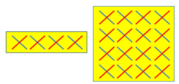 Fig. 1. The illustrations of a cross-polarized linear array with 8 elements (left) and a cross-polarized rectangular array with 32 elements (right).
Typically, a linear antenna array arranged along one dimension is assumed for most MIMO studies. So, only the users with different azimuth directions are separable in MU-MIMO. Recently, based on the possibility of using active antenna systems (AAS) at base stations of the next-generation cellular networks, two-dimensional rectangular antenna array has been suggested [3]. With such deployment, both azimuth and elevation angles of the downlink beam direction can be jointly steered [4]. Furthermore, as the number of transceiver units (TXRUs) can be much larger than the legacy systems, a much higher beamforming gain can be attained. This context can be referred to 3D-MIMO, and 3GPP is currently considering adopting this technology as a distinguishing feature of future releases of LTE [5]. A legacy cross-polarized linear array (horizontal only) with eight antenna elements and an evolved cross-polarized rectangular array with 32 antenna elements are shown in Figure 1.
As both azimuth and elevation of the beam can be steered with two-dimensional rectangular antenna array, the beam can be directed in a more precise fashion. Therefore, the link quality experienced by the targeted user can be boosted as the
emitted signal power is more focused. On the other hand, the interference power leakage to other users in vicinity can be dramatically reduced. These properties may lead to tremendous performance gain in terms of spectral efficiency, and hence making it a promising enabling technology of 5G. There are several possible use cases of 3D-MIMO schemes, such as vertical sectorization, user-specific beamforming, and full dimension MIMO (FD-MIMO).
The main objective of this article is to provide an overview of 3D-MIMO technology, including the architecture of two-dimensional active antenna array, transmission schemes based on 3D-MIMO, and some potential standard impacts to the existing 3GPP LTE standard.
II. ANTENNA VIRTUALIZATION FOR 3D-MIMO
At physical layer of a traditional MIMO transmitter in LTE,each layer of data undergoes several steps of processing such as channel coding, interleaving, modulation, and antenna mapping.Moreover, the step of modulation comprises serial-to-parallel (S/P) conversion, inverse fast Fourier transform (IFFT) and cyclic prefix (CP) insertion as orthogonal frequency division multiplexing (OFDM) is employed as the air-interface. In spatial multiplexing modes, one or more layers are mapped to multiple logical antenna ports via precoding [6]
As aforementioned, with deployment of 2D active antenna arrays, the number of antennas and transceiver units (TXRU)can be can be much larger than the legacy systems. Note that a TXRU is simply a chain of radio-frequency (RF) circuits, the input and output signals of which are digital and analog,respectively. Therefore, depending on the configurations and requirements, further virtualizations might be needed for mapping between logical ports and TXRUs, as well as mapping between TXRU and antenna elements. The topology of a general 3D-MIMO transmitter with P≥1 ports, Q≥1 TXRUs,and M≥1 antenna elements is depicted in Figure 2. Typically we have M ≥ Q ≥ P. Consider a spatial multiplexing scenario where L layers of data are sent concurrently,a PXL precoding matrix(denoted as )is applied in baseband, so the overall virtualization matrix, , can be written as where both
  are digital-domain operations that can be frequency-selective, while TXRU virtualization matrix
  represents an analog wide-band operation in time-domain [7].
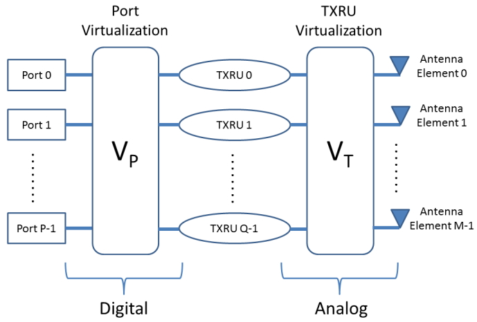 Fig. 2. 3D-MIMO transmitter architecture.
Depending on the 3D-MIMO scheme under consideration,antenna port virtualization can be either based on beamforming or one-to-one mapping. In the latter case, is simply an identity matrix. Antenna port virtualization is discussed in more details in the subsequent section, and here we aim to examine the effects of TXRU virtualization on radiation patterns. In general, there are two types of TXRU virtualizations [8]:
Type 1: TXRU virtualization based on subarray
Type 2: TXRU virtualization based on full-connection
In Type 1 virtualization, an array of antenna elements array is partitioned into Q disjoint subsets, and the TXRUs are associated to these antenna elements subsets in a one-to-one fashion, as shown in Figure 3.
In Type 2 virtualization, each TXRU is connected to all M antenna elements, while the signal of each antenna elements is a linear combination of outputs from multiple TXRUs, as shown in Figure4.
Note that the beam direction in both types of TXRU virtualization is determined by the complex weightings, which corresponds to phase shifts in time-domain.
For virtualization based on sub-array, the transmitted signal vector q at the M co-polarized antenna elements within a column can be modeled as:
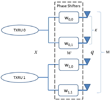 Fig. 3. TXRU virtualization based on sub-array.
In Type 2 virtualization, each TXRU is connected to all M antenna elements, while the signal of each antenna elements is a linear combination of outputs from multiple TXRUs, as shown in Figure 4.
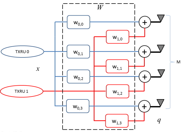 Fig. 4. TXRU virtualization based on full-connection
Note that the beam direction in both types of TXRU virtualization is determined by the complex weightings, which corresponds to phase shifts in time-domain.
For virtualization based on sub-array, the transmitted signal vector q at the M co-polarized antenna elements within a column can be modeled as:
where x is a TXRU signal vector at MTXRU TXRUs, and w is TXRU virtualization weight vector with entries defined as:
The parameters K, dv, θetilt denote the number of antenna elements in corresponding to a TXRU,the vertical antenna spacing (in term of wave length λ), and the electrical tilt angle of the main beam, respectively.
For virtualization based on 1D full-connection, the signal is defined as:
and the elements of W are defined as:
Here we show the resultant radiation patterns for both types of TXRU virtualizations. For subarray scenarios, the beam pattern of TXRU virtualization with 64 antenna elements and 16 TXRUs are illustrated in Figure 5 and 6, where dv=0.8λ and dv=0.5λ respectively. Moreover, Figure 7 and 8 show the beam pattern of TXRU virtualization with 64 antenna elements and 32 TXRUs, where dv=0.8λ and dv=0.5λ respectively. With a smaller dv, a beamwidth wider than 3dB and a larger gain difference between the main beam and the first sidelobe can be observed. Further, the main beam in cases with 32 TXRUs is relatively flat compared to that with 16 TXRUs.
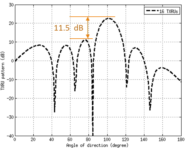 Fig. 5 Beam pattern with subarray virtualization with 16 TXRUs and dv=0.8λ
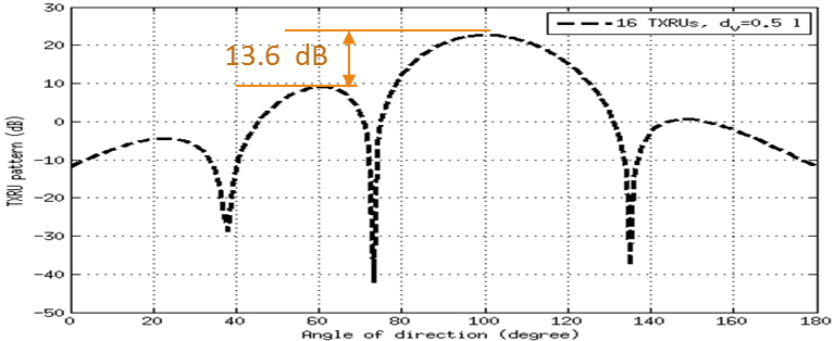 Fig. 6 Beam pattern with subarray virtualization with 16 TXRUs and dv=0.5λ
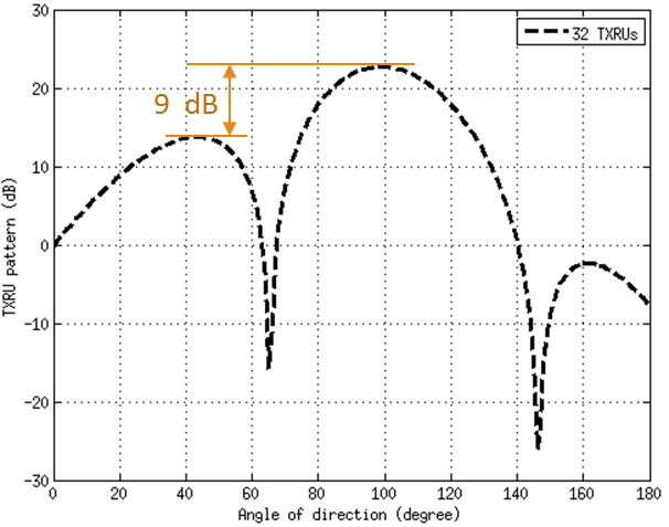 Fig. 7 Beam pattern with subarray virtualization with 32 TXRUs and dv=0.8λ
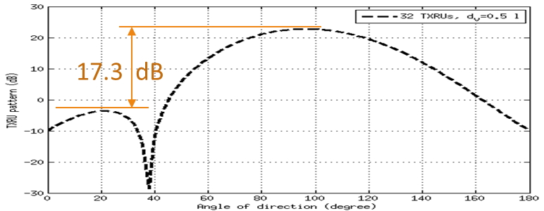 Fig. 8 Beam pattern with subarray virtualization with 32 TXRUs and dv=0.5λ
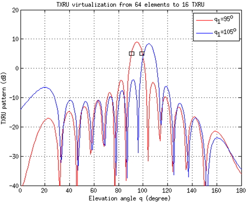 Fig. 9 Beam pattern with full-connected virtualization with 16 TXRUs and dv=0.5λ
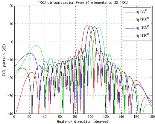 Fig. 10 Beam pattern with full-connected virtualization with 32 TXRUs and dv=0.5λ
III. 3D-MIMO SCHEMES
In this sections, we discuss some of the potential schemes based on 3D-MIMO technology.
A. Vertical Sectorization
By utilizing the flexible beam shaping capability of AAS, a sector in a conventional cellular network can be further split up into two cells with different identities. To be specific, a pair of vertical beams each having its own electrical tilt angle are dedicated to form two cell sectors that respectively correspond to inner and outer regions of the cell coverage [9]. For instance,in Figure 5, the users in the inner sector (cell 1) are served by the beam with electrical tilt angle θ1, and the outer sector (cell 2)formed by electrical tilt angle θ2 is responsible for the users further away from the center. Note that the operation of vertical sectorization is entirely transparent to the users, and there are barely any standard impacts. Apparently, vertical sectorization brings cell-splitting gain and hence improves system capacity.
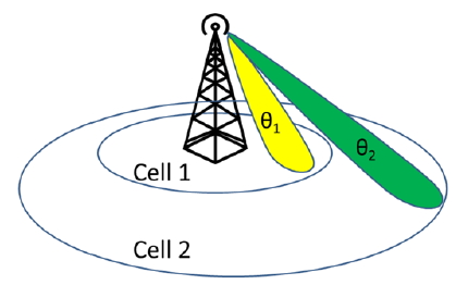 Fig. 11. Illustration of vertical sectorization
B. User-Specific Beamforming
With user-specific beamforming, precoding is applied to pilot signals to form a narrow beam for channel measurement at the user terminal. In this case, antenna port virtualization described in Section II is no longer one-to-one mapping as inconventional systems, instead a virtualization matrix is applied over the reference signal ports. Thus, this scheme is more appropriate for cases where the number of antenna ports is smaller than the number of available TXRUs. Each column of corresponds to a specific beam direction, so a user is able to measure its channel status under different beam patterns.The measurement report, including the favorite beam indexand/or the channel status information (CSI), is then reported by the user to the base station to aid scheduling and link adaptation.Note that the beamforming vector can be determined by the base station itself or based on the instantaneous channel condition of the user[10], which can be acquired by the base station via, for example, uplink sounding in time-division duplex (TDD) operation mode.
C. FD-MIMO
Recently, a new paradigm dubbed as Massive-MIMO has emerged and received consideration attentions from researchers
in both academia and industry [11]. The theoretical analysis of which indicates that significant performance gain can be achieved when a very large number of antenna ports are employed for multi-user MIMO operation. In particular, conventional adverse effects such as fading and intra-cell interference would vanish if the number of antenna ports is increased to infinite. FD-MIMO can be regarded as a special case of Massive-MIMO, with a two-dimensional rectangular array of antenna being employed at the transmitter [12], and the number of antenna ports is the same as the number of available TXRUs. In contrast to user-specific beamforming elaborated previously, the antenna ports are not precoded in FD-MIMO and is merely an identity matrix. With the additional capability of steering beam in both horizontal and vertical domain, Massive-MIMO performance can be enhanced due to further spatial separation in vertical domain. For instance, in Figure 12, two users at different height levels (e.g. located atdifferent floors of a skyscraper) can be served simultaneously based on MU-MIMO in spite of their similar azimuth anglewith respect to the base station.
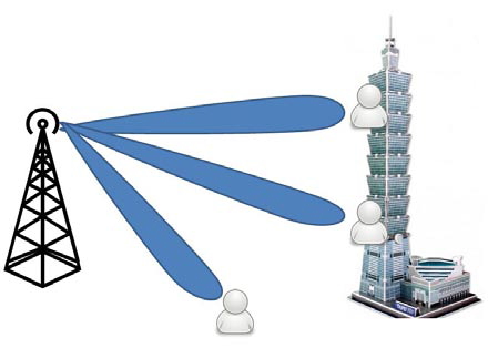 Fig. 12. Illustration of FD-MIMO, where multiple users with the same azimuth angles but different elevation levels can be co-scheduled in MU-MIMO oper
IV. CHANNEL STATE INFORMATION (CSI) ACQUISITION
In practice, several issues have to be addressed to support 3D-MIMO in the existing 3GPP LTE standard. One of the most challenging aspects for the physical-layer design would be the overheads for reference signals and channel state information(CSI) reporting.
In the current LTE Release 12 specification, the reference signals for CSI measurement (the so called CSI-RS) can only support up to 8 antenna ports. A new design may be required for schemes such as FD-MIMO where the number of antenna ports can be much larger than 8. A recently proposed method based on Kronecker product approximation that addresses such issue without causing too much specification impacts is described below.
It has been found that the channel matrix can in fact be approximated by the Kronecker product of channels separately measured in horizontal and vertical domains of the 2D array[13]. Thus, one possible approach would be to configure two independent sets of CSI-RS that dedicate to measurements for horizontal and vertical channels. As long as the number of antenna ports in each domain (horizontal or vertical) is fewer than 8, two legacy CSI-RS resources can be configured to enable separate channel measurements. Hence, the user can derive and report horizontal and vertical precoding matrices,WH and WV respectively (utilizing two CSI processes); then the base station is able to construct the overall precoding matrix via Kronecker product between WH and WV
Due to its simplicity, the method has been discussed extensively in recent standard meetings of 3GPP LTE.However, whether such approximation can provide acceptable accuracy is still an open problem and therefore requires further investigations.
V. SUMMARY AND CONCLUSIONS
This article introduces the concept and recent developments of 3D-MIMO, including the essential architecture and schemes that are currently considered for adoption in 3GPP LTE. We have also briefly discussed the issues relating to the overheads of CSI measurements and reporting, and a potential way to resolve the problem. To realize 3D-MIMO, many other issues should be addressed in the future, and it has therefore created numerous research opportunities.
REFERENCES
3GPP TS 36.213, V11.0.0 (2012-09), Physical layer procedures
C. Lim, T. Yoo, B. Clerckx, B. Lee and B. Shim, “Recent trend of MU-MIMO in LTE-Advanced”, IEEE Commun. Mag., Vol. 51, Mar.2013.
Huawei, “Active Antenna System: Utilizing the Full Potential of Radio Sources in the Spatial Domain”, Nov. 2012.
H . Halbauer, S. Saur, J. Koppenborg, and C. Hoek, “3D Beamforming:Performance Improvement for Cellular Networks”, Bell Labs Tech.Journal, Vol. 18, No. 2, Aug. 2013.
RP-141644, New SID Proposal: Study on Elevation Beamforming/Full-Dimension (FD) MIMO for LTE. Samsung, Nokia Networks. Edinburgh, Scotland, UK, 9 – 12 Sept. 2014.
S. Sesia, I. Youfik, and M. Baker, “LTE - The UMTS Long Term Evolution: From Theory to Practice”, 2nd Edition, Wiley, 2011.
R1-151638, “Discussions on tradeoff of CSI-RS and feedback enhancement”, Samsung, Apr. 2015.
R1-143884, “TXRU Modeling and Antenna Virtualization for FD-MIMO”, Samsung, Oct. 2014.
R1-144190, “High Level View of Schemes for EBF/Full Dimension MIMO”, Nokia, Oct. 2014.
R1-151911, “Enhancements related to precoded CSI-RS based schemes”,Nokia, Apr. 2015.
E. G. Larsson, F. Tufvesson, O. Edfors, and T. L. Marzetta, “Massive MIMO for Next Generation Wireless Systems”, IEEE Commun. Mag.,vol. 52, no. 2, pp. 186-195, Feb. 2014.
Y. Kim, H. Ji, J. Lee, Y. H. Nam, B. L. Ng, I. Tzanidis, Y. Li and J. Zhang,“Full dimension mimo (FD-MIMO): the next evolution of MIMO in LTE systemsFull dimension mimo (FD-MIMO): the next evolution of MIMOin LTE systems”, IEEE Wireless Commun., Vol. 21, No. 2, Apr. 2014,pp.26-33.
R1-150567, “Precoding Schemes for Elevation Beamforming and FD-MIMO”, NTT Docomo, Feb. 2015.
Ping-Heng Kuo is currently a senior engineer of Information and Communications Research Laboratory (ICL), Industrial Technology Research Institute (ITRI), Hsinchu, Taiwan.
Tsung-Hua Tsai is currently a senior engineer of Information and Communications Research Laboratory (ICL), Industrial Technology Research Institute (ITRI), Hsinchu, Taiwan.
