Konstantin Koslowski, Wilhelm Keusgen, Thomas Haustein, Fraunhofer Heinrich-Hertz-Institute, Berlin, Germany
This paper presents the concept of wireless backhaul for small cell deployments using millimeter-wave links in a meshed topology for dynamic hot spot capacity allocation and resilience to individual link overloading or link failures. The Millimeter-wave backhaul network relies on per link autonomous link operation and optimization and its core functionality as a backhaul transport network is orchestrated in a centralized fashion taking parameters like link capacities, link aggregation, multi-path routing, routing segment congestion, latency and packet jitter into consideration. This will allow the wireless backhaul network to be operated in an energy and capacity optimized way providing flexible and cost effective backhaul solutions for dense and ultra dense small cell deployments being essential for the high capacity 5G wireless access at millimeterwave spectrum or below 6 GHz.
I. Introduction
Standardization its on its way along the 5G roadmap being set up in Spring 2017 focusing on Enhanced Mobile BroadBand (eMBB) as the main use case group for 3GPP’s release 15 and 16. Other use case groups like Mission Critical Communication (Ultra Reliable Low Latency Communication, URLLC) and Massive Machine Type Communication (mMTC) are use cases which will get supported by more and more features in release 16 onwards. Therefore, the targets in eMBB are on further network densification with small cells towards ultra-dense networks (UDN) and bandwidth extensions into the 3.5 GHz range and beyond 6 GHz into the millimeter wave spectrum to increase the provided wireless access capacity per area by a factor of 100-1.000. A resulting rainforest like architecture with small and very small cells in coverage within a macro cell [1] and concepts how to access and share the new millimeter wave spectrum can follow newly established sharing concepts as proposed in [2]. Reference [3] showed that about 30 mmW small cells within the coverage area of a macro cell are needed to provide a capacity increase of about 1.000 - 10.000 using 60 GHz and 2 GHz channel bandwidth as in IEEE802.11ad. With such increase in wireless access capacity, a dramatic demand of backhaul and intercell capacity comes along. Since fiber backhaul in many cases in infeasible or prohibitive from a cost perspective, wireless backhaul to fiber or cable based aggregation points like e.g. macro base stations are considered as a promising solution. While these ”last mile” backhaul connections may require to bridge several hundred meters over the air, capacity requirements go into the 1-100 Gbps range excluding wireless backhaul in spectrum below 6 GHz simply by the available bandwidth. Therefore, millimeter wave spectrum at 28, 39 or 60GHz are currently considered as good candidates for so called fixed and mobile wireless access and backhaul solutions as considered in [4] and [5].
Millimeter wave wireless communication requires beam forming at each side of the link and can achieve very signal to noise ratios to support high order modulation and coding schemes in direct line of sight (LOS) links. Since mobile networks have to support user mobility, handover between adjacent cells has to be supported with traffic being forwarded and/or rerouted from one access point (AP) to the next. In order to reduce the overall routing path length, and congestion on aggregating links, a meshed or partially meshed topology will provide a good mix for routing path diversity, multiplexing and resilience in case of link failures. Beyond ultra high speed backhaul low latency for new e2e services are targeted for many low latency applications like computation offloading, ultra high data rate downloading of prefetched data, or latency sensitive applications to be hosted near by in the so called mobile edge cloud.
The European-Japanese collaboration project 5G-MiEdge [6] targets the combination of two key 5G Phase II technologies: Millimeter-wave transmission and mobile edge computing (MEC) which in a close interaction open many new possibilities by shifting the focus of system design to applications [7]. This paper focuses on the design of a wireless millimeter wave backhaul network with a flexible mesh topology that can adapt and meet the ever-changing demands on 5G networks. Due to the increased density of 5G access points and moving hot spots in time and geographical location the load at each access node will change more dynamically than it is observed in the current networks. To satisfy these demands without sacrificing performance or resulting in inefficiencies of variably loaded networks the topology itself and the established routing schemes need to become flexible.
This leads to fundamental questions regarding novel network architectural design criteria e.g.: What are the functional building blocks for a network to become flexible and being able to adapt to dynamically changing or mixed sets of requirements with partially contradicting objectives? The use of millimeter-wave links enables wireless data rates of multiple Gbps and extremely low latencies combined with beam forming technologies a link range of several hundred meters at the cost of limited to very low interference levels on other links in the vicinity. Making use of the beam steering capabilities with array antennas of larger aperture and large number of antenna elements 64 - 512 like presented by various companies as SOTA prototypes such link nodes can be used to build a backhaul network with a flexible mesh topology. The flexibility in connecting nodes over beam steered links in a dynamic fashion allows to establish more links if needed e.g. to support an areas of high capacity demand, while other areas in the network might be sufficiently supported by a fewer number of links and routes to be available as backhaul at a given point of time. Due to the large bandwidths with millimeter-wave communications links and short transmission frames, low latency comes de facto for free as a package allowing multi-hop traffic routing without sacrificing substantial performance with respect of additional latency. Furthermore, the combination with mobile edge computing enables e.g. offloading of computational tasks from multiple small cells covering a dedicated area with time sensitive applications as e.g. extended sensor sharing for automated driving and provide results within milliseconds.
In order to efficiently manage such a flexible mesh backhaul network a centralized orchestration is needed. In such architecture, a central controller will monitor the load on individual parts of the network and constantly optimize traffic routing, local guidelines for links and routing options and initiate even topology updates. Following such rationale the central orchestrator can provision a large area and longer term optimized networks configuration, while client-to-server links inside the network or beyond the boundaries of the wireless mesh network can build on provide link metrics, load status updates etc. in order to make local and distributed decisions on preferred traffic routing, data traffic splitting, aggregation and other specific changes in the connectivity setup in order to meet service specific requirements and network operation specific metrics like e.g. shortest route preference, balance traffic distributions, energy reduction at the same time.
An exemplary topology is displayed in figure 1. Numerous small cells are deployed inside the coverage of a macro cell. The small cells are equipped with computation capabilities and storage capacities connected via the mesh topology with multiple redundant links. The routes and links are orchestrated by the backhaul network orchestrator, using the macro cell network as a control channel and constantly optimizing the resulting backhaul network. The paper is organized as follows: After introduction of the overall concept, details on the small cells distribution and resulting requirements for the backhaul architecture concept are described in section II. Section III explains more details about the flexible mesh topology, which is controlled by the centralized backhaul network orchestrator (C-BNO) and decentralized link and routing decision units (D-BNO), further outlined in section V. Section VI discusses early first results of the implemented concept followed by the conclusion in section VII.
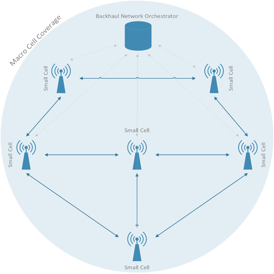 Fig. 1. Heterogeneous Network of small cells inside macro cell coverage
II. Small Cells: Concept and Implementation
When millimeter-wave spectrum will be introduced for wireless access 5G networks, wireless alternatives for backhaul will become a key component for the 5G network architecture - since it’s seems almost impossible to provide fiber connections to every new small cell base station. A more realistic approach considers fiber deployments at down to macro cell level and filling the gaps to the infrastructure below with self-backhauling small cells, while including the existing 4G network as an overlay with C/U (control/user) plane split [8]. The 4G overlay can then provide a control channel and connect lightly populated areas that do not immediately require 5G ultra wide band wireless access.
The millimeter wave self-backhaul capacity allows the small cells to create a meshed backhaul network providing highspeed connections, flexible traffic steering, traffic routing and, using the proposed concept, even a flexible topology. To achieve these goals all small cells in our system deployment in Berlin, displayed in figure 2, are equipped with at least two millimeter wave front-ends combined with beam forming reflect arrays, resulting in a 6° beam and a gain of 24 dBi. Each front-end can be rotated by 360° horizontally and 30° vertically to point and focus the beam on other small cells within a range of up to 200 m, as detailed in reference [9]. Due to the modular design concept each small cells can incorporate a variable number of front-ends for backhaul, customized to fit perfectly into the deployment scenario. The bottom compartment of the enclosure contains a computation core, enabling Mobile Edge Computing (MEC) capabilities such as offloading of computational tasks from the mobile devices to one or multiple small cells and content caching/prefetching.
 Fig. 2. Small cell with computation core and two beam steering elements
These features features can help to further increase the network efficiency. Executing computational tasks on the small cell instead of using cloud services far away in the core network provides benefits in two ways: First, it drastically reduces the amount of data that needs to be exchanged with the core network and second, it results in the lowest possible latency for cloud computation, enabling the offloading of tasks that need to be processed close to real-time, e.g. virtual reality applications, while reducing battery drain on the mobile device. It also enables whole new use cases like automated driving with very stringent requirements [10] of
- Data-rate ≥ 1 Gbps
- End-to-end latency ≤ 10 ms
- Communication Range of up to 200 m
in order to constantly send raw sensor data to the roadside units - which can be small cells or macro cells - and in return receive the latest HD maps for the next few kilometers. When using the current state of the art technology, such applications are impossible without sacrificing either performance and resulting in noticeable delays.
Another important aspect when increasing the density of small cells is their power usage. Due to the dynamic load in a HetNet in different daytimes, on recurring events like rush hour and also on random events not only the routes and links need to be controlled, but also the power. A small cell can switch between different power states, disabling some of the functionality and offering different power saving levels, but also taking certain time periods to recover and be fully operational again. This can be done because the HetNet is able to function, at reduced performance, with all small cells being powered down and just the macro cell being active. For the small cells, there’s the default power state with all links aligned and active, while guaranteeing the highest possible performance, it also requires most power. Now there are hybrid states with some links being fully active, while others are powered down, this already enables some savings and bringing the link back up, when still aligned, takes less than one second. In case all links are disabled, the entire small cell can be sent to sleep, reducing the power usage to a bare minimum when just waiting for a power-on command. Waking up from the lowest state will then take around 5 seconds, so the orchestrator needs to plan ahead in case the small cell is needed again.
III. Backhaul Network with Flexibile Mesh Topology
The small cells and their millimeter wave backhaul links introduced in the previous section can form various topologies including partially or fully meshed, as long as there are line of sight deployment opportunities and distances between on each link less than 200 m. Beam steering with adaptive point to point connectivity featuring automatic link alignment and optimization allow dynamic topology reconfigurations and associated optimizations. In the next two paragraphs, the reconfiguration of links and adaptive packet re-routing will be elaborated in more detail.
A. Adapt Routes
Adaptation of routing should be a very fast, almost instant procedure. New routing tables can be set either for different quality of service (QoS) classifications, depending on latency and data rate requirements, or purely for the purpose of packets reaching their final destination. With QoS classification, packets from the same intermediate source and to the same final destination may be passed on to different routes in order to meet the associated requirements. This dynamic traffic steering is further described in detail in section IV. Besides this QoS handling there are static fallback routes set by the orchestrator in case an active link is suffering from blockage or other degradation effects. With our proposed mesh topology the number of hops will only increase slightly, keeping the added latency to a bare minimum and making sure the packets reach their destination within a given latency budget. If the link degradation is resolved within the defined link blockage timeout tblockage the traffic is re-routed along the previous routing path again, but if this timeout is exceeded the central backhaul network orchestrator is notified and may initiate further actions like calculating alternative routing options or optimizing the overall routing tables within a certain network region.
B. Adapt Links
Link blockage is a severe link performance degradation and has to be responded with immediate actions allow rerouting of packets over alternative backhaul links constantly monitored about their link availability, latency and load. If a link blockage event occurs is the link can not be reestablished within a well defined link outage time toutage, the central backhaul network orchestrator will be informed about a local re-routing decision of all or part of the traffic which suffered from the link loss, and most likely initiate a optimization procedure considering a link loss within part of the mesh. The decentralized orchestrator will trigger the affected front-ends to realign on both sides exploiting e.g. first order reflections on buildings or ground reflections. If this is not successful alternative link partners are considered and associated links search for and build using link opportunity list for the vicinity of each small cell. This adaptation procedure usually takes a few seconds and renders the affected links unusable during this time, therefore the possible resulting topologies are carefully evaluated by the applied algorithms, detailed in section V.
IV. Dynamic Traffic Steering and Routing
Depending on the classification, traffic can be routed differently. Simple traffic routing, if the requirements are rather relaxed, and so-called traffic steering in case they are more challenging. With traffic steering, routes are selected to satisfy a maximum end-to-end latency, or minimum end-to-end data rate. While this is nothing new, the proposed concept opens up a new flexibility. Not only can existing routes be used to forward the packets and meet their requirements, the links can be realigned, adapting the entire topology in case the requirements can not, or no longer, be satisfied. This adds another level of freedom to the orchestration algorithms, but does come at a price because changing links does take multiple seconds in which the traffic must be redirected along other paths. Optimizing the orchestrator to take this downtime into consideration so the links are actually ready right before they are needed will significantly reduce the downtime, possibly eliminating it entirely and therefore dramatically increase the efficiency of the flexible mesh network.
V. Backhaul Network Orchestration
Backhaul network orchestration is divided into two parts, starting with the central backhaul network orchestration (CBNO). There is one single instance that orchestrates the whole heterogeneous network with the small cell mesh and the overlaying macro cell, explained in section V-A. The necessary counterpart is the decentralized backhaul network orchestration (D-BNO) with an individual instance running on each small cell, detailed in section V-B. Section V-C will explain the details on optimization of routes and links.
A. Centralized Backhaul Network Orchestration (C-BNO)
With an overview and control of the entire HetNet the centralized backhaul network orchestrator is acting as a SDN controller and can modify individual routes and links to optimize the resulting HetNet. Modifying routes is a fast, almost instant task and does not result in actual network downtime, but the margin for optimization is also limited. If there’s just one available link to a crowded area, routing can not change that.
On the other hand the modification of links will terminate all connectivity for a few seconds until the beam steering is done and new links are established. This process has a much higher optimization margin, especially when considering link aggregation: Having multiple links between adjacent small cells when a certain area is heavily loaded.
B. Decentralized Backhaul Network Orchestration (D-BNO)
The dynamic traffic steering, explained in the previous section IV is controlled by the decentralized backhaul network orchestrator, running individually on each small cell and constantly exchanging metrics with and receiving commands from the C-BNO.
It is also responsible for taking immediate actions on temporary or long-term link failure. Due to the millimeter wave technology, blocking a link will lead to a temporary link failure. The blockage itself can be just a bird passing by, a person walking on the street, a vehicle or even extreme weather conditions, see reference [11]. Now the first action to take on blocked links is to start re-routing all traffic using the previously set fallback links, this may result in a slightly higher latency or lower throughput but is still preferable to losing packets. If the blockage was caused by a passing object, it will resolve quickly and the small cell continues normal operation. But there may also be long term blockage, lasting longer than the previously mentioned tblockage timeout. In this case the C-BNO needs to be notified of the situation and act accordingly, as explained in the previous section. Each D-BNO periodically sends metrics to the C-BNO, including measurements for the small cell itself:
- Temperature
- Humidity
- Power usage
For the computation core:
- Computation load
- Cache usage
And for each link:
- Link margin
- Latency
- Availability in the past hour
These metrics are evaluated and used to optimize the routing, mesh topology and power usage of the heterogeneous network.
C. Backhaul Network Orchestration Optimization
Optimization of the backhaul network starts when the Het- Net is activated for the first time and uses a global overview for finding possible links between all existing small cells. This means that there is a possible link between all adjacent small cells that may have a line of sight and a distance of less than 200 m. Now all identified links are established and measured for actual throughput, latency and overall link quality, because there may be frequent blockage or other degradation effects that could not be initially identified. The first step in deciding which links to use is making sure each small cell is connected with at least one link. After this, the remaining links are established based on their link quality and providing the necessary throughput in more demanding areas of the heterogeneous network. Now the mesh topology is set up and the service starts up. But given the dynamic conditions of the HetNet, like efficient power usage and blocking events, the optimization needs to be constantly updated with the latest events, requirements and link metrics to perform necessary changes to the topology, like powering up/down or realignment of certain links. The results, presented in section VI, will show some more details on the optimization margin of these methods.
VI. Results and Evaluation
To verify the proposed concept, a number of tests and measurements were conducted. We started with a simple pointto-point link setup, followed by a multi-hop link scenario. The measured metrics were then used for a larger scale network analysis using numerical simulations to investigate the behavior of the rerouting process.
A. Hardware measurements
The measurements with real world hardware were setup to measure basic metrics like throughput, packet loss and latencies for a single point-to-point link and a multi-hop setup to estimate the added latencies when forwarding packets from one millimeter wave backhaul node to another one going through the entire protocol stack.
1) Point-to-Point Measurement: We started with a simple point-to-point link, using the reflect array setup for beam forming and 802.11ad front-ends on both sides. With this setup, the link node distance was stepwise increased from 1 to 100 meters and the following metrics were measured:
Where RSSI (Received Signal Strength Indicator) is defined as the power that is measured in a received radio frame. Figure 3 shows the measured RSSI and latency.
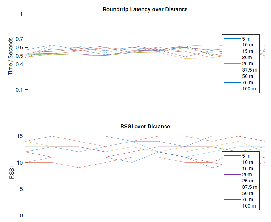 Fig. 3. Latency and RSSI in P2P measurements
As expected, the latency basically does not change with increasing distance and is varying slightly around the average of 520 ms. The RSSI is measured in intervals, 15 being the maximum and 0 the minimum. When placing the frontends directly next to each other the RSSI is constantly at the maximum of 15. At 100 meters, it varied between 10 and 11.
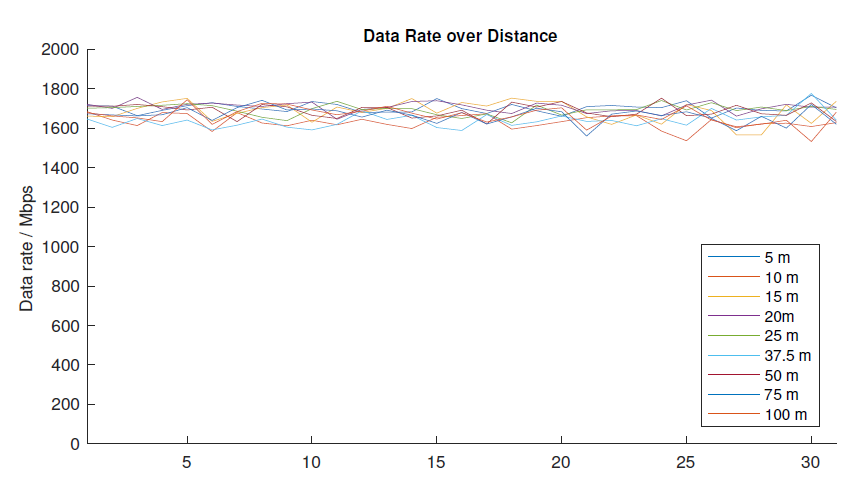 Fig. 4. Data rate in P2P measurements
Comparing the different distances, there is a slight decrease in the measured RSSI level, but during this measurement the modulation and coding scheme (MCS) is kept at a fixed level, using a coding rate of 13⁄16 with a π⁄2 -QPSK. As a result, the data rate, displayed in figure 4, reaches roughly 1.7 Gbps and does not degrade within 100 meters.
2) Multi-Hop Latency Measurement:
The multi-hop measurement setup, shown in figure 5 uses a source node, a forwarding node and a destination node in order to include a classical forwarding or routing node with its associated protocol stack induced added latencies.
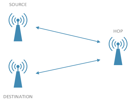 Fig. 5. Multi-hop setup
By varying the number of hops the added end to end latency between source and destination can be separated in a latency contribution for each wireless backhaul link and an additional latency contributed by the packet forwarding across the protocol stack connecting two adjacent 802.11ad units via Ethernet interfaces.
The measurement results are displayed in figure 6. The roundtrip latency for two links and one intermediate hop varies between 0.9 and 1.2 ms, with an average of 1.06 ms. Compared with the single hop latency measurements averaging at 520 ms round trip time for each link a negligible latency overhead of about 20 ms was measured at the intermediate hop for forwarding packets between two 802.11ad frontends.
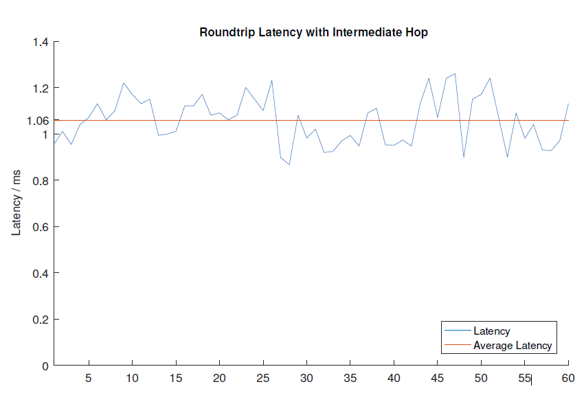 Fig. 6. Latency in Multi-hop Measurements
B. Analysis
The measured data and metrics were fed into our simulation platform to analyze the re-routing process and the achievable performance for an artificially enlarged meshed backhaul network scenario. Figure 7 shows the topology used for the investigation.
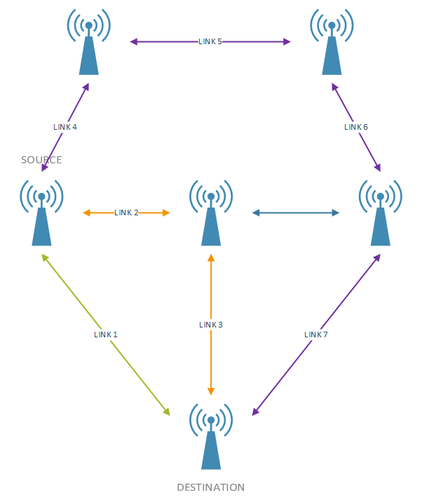 Fig. 7. Analysis topology
There is one small cell marked as SOURCE and one as DESTINATION and there are three possible routes in between these cells:
- Route1, colored green.– LINK1
- Route2, colored orange.– LINK2, LINK3
- Route3, colored purple.– LINK4, LINK5, LINK6, LINK7
Route1 using a single direct connection is favored by the optimization algorithms. Keeping backup routing options at hand in case of an event that the link might be blocked or lost, additional routing options are kept in a routing table. These alternative routes do include additional hops and therefore come at the cost of an increased end-to-end latency, but for most applications, these routes are still feasible options for latency requirements of a few ms.
To analyze the link selection algorithm under more realistic load situations the links were fed with variable loads, as shown in figure 8.
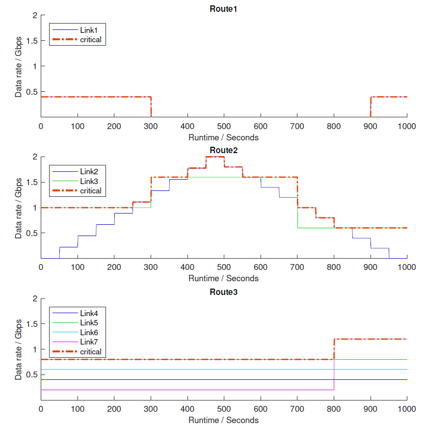 Fig. 8. Available routes in analyzed topology
Since each link has just a certain supportable data rate, an end-to-end route throughput is determined by the critical margin of the most loaded link. This is shown by the orange colored dotted line in the figure. This is trivial for the first route, consisting of a single link, but when looking at route2 it gets more interesting, the critical link changing between the defined links, as their usage changes. The links in the third route are under a constant load, until link7 gets loaded at the end.
The assumed application in our example requires a constant data-rate of 400 Mbps. When looking at the available routes in figure 8, one can already see that the available data rate in the first route will not be sufficient during the whole duration of the experiment and the traffic needs to be re-routed.
Figure 9 shows the used routes and their used data rates in blue on the left side and the resulting latency in orange on the right side.
As one would expect, the orchestrator starts with selecting the shortest route, adding the needed 400 Mbps to the route1 usage and offering an extremely low latency of just slightly above 500 ms. When link1 breaks due to an blockage event at t = 300 and link2 of route2 is already under a high load, the orchestrator selects the third route to be used, resulting in a latency of roughly 2.2 ms, but still meeting the 400 mbps data rate requirements. While using the other available links, the orchestrator is reconfiguring link1. After t = 700 the situation on the second route relaxes and the orchestrator can switch to that route, reducing the latency to just 1.1 ms until finally, at t = 900 link1 is recovered and route1 becomes available, the traffic is again routed over the direct connection between source and destination. The orchestrator is constantly optimizing the routing and always selecting the best available route to meet the application requirements in the best possible way.
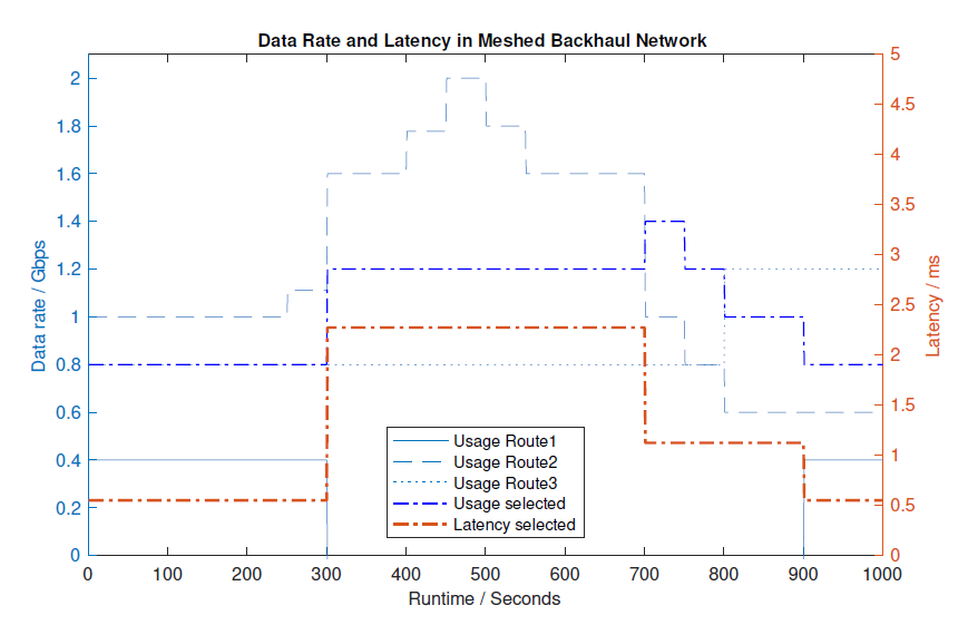 Fig. 9. Selected route in analyzed topology
VII. Conclusion
The paper introduces a novel concept of millimeter wave meshed backhaul networks with a hierarchical network orchestration based on SDN. Bridging small cells in a HetNet scenario and providing connection to the macro cellular network millimeter wave backhaul solutions are expected to become a key solution component for the rollout of 5G networks. Our proposed concept allows the wireless backhaul network to meet the new 5G requirements of end-to-end data rates and latencies by the combination of millimeter wave backhaul links, meshed multi-connectivity between routing nodes, and mobile edge computing for provisioning of storage and calculation capacity right within the network. The SDN based node reconfigurability provides the ability to flexible reconfigure individual routes and the topology, which becomes a huge benefit when deploying 5G networks in terms of performance, flexibility deployment and runtime costs and dynamic optimization.
The paper is reporting early results of an ongoing and further continued 5G network setup in 5G-Berlin for early prototyping and field trials of 5G technology components in a real world environment. Our research plans include a further extended deployment of the HetNet and the millimeter wave backhaul links in the 5G-Berlin testbed, complimented by larger scale simulations and refining of the implemented algorithms to further increase the performance. This research will contribute to projects like 5G-MiEdge [6] and others conducted at the Fraunhofer Heinrich-Hertz Institute in Berlin.
Reference
[1] M.D. Mueck, et al, Global standards enabling a 5th Generation Communications system architecture vision, Globecom Workshops, 571-576, 2014
[2] M.D. Mueck, et al, Licensed shared access for wave cellular broadband communications, Cognitive Cellular Systems (CCS), 2014 1st International Workshop on, 1-5
[3] K. Sakaguchi, et al, Millimeter-wave evolution for 5G cellular networks, IEICE Transactions on Communications 98 (3), 388-402, 2015
[4] A. De La Oliva, et al, Xhaul: toward an integrated fronthaul/backhaul architecture in 5G networks, IEEE Transactions on Wireless Communications 22 (5), pages 32-40, October 2015
[5] E.C. Strinati, et al, 5G CHAMPION-Rolling out 5G in 2018, Globecom Workshops, 2016 IEEE, 1-6
[6] 5G-MiEdge, H2020 5GPPP, EU-JP collaboration project, https://5gmiedge. eu/
[7] V. Frascolla, et al, 5G-MiEdge: Design, Standardization and Deployment of 5G Phase II Technologies, CSCN 2017
[8] R. J. Weiler, et al, Enabling 5G Backhaul and Access with millimeterwaves, EuCNC 2014
[9] T. Visentin, et al, Dual-Polarized Square-Shaped Offset-Fed Reflectarray Antenna with High Gain and High Bandwidth in the 60 GHz Domain, EuCAP 2015
[10] 5G-PPP, White Paper: 5G Automotive Vision, October 20th, 2015
[11] K. Liebe, MPM - An Atmospheric Millimeter-Wave Propagation Model, International Journal of Infrared and Millimeter Waves, Vol. 10, No. 6, 1989
Acknowledgment
Parts of this work were supported by the Joint European- Japanese collaboration project 5G-MiEdge under grant no. H2020-723171 and the European project 5G-Crosshaul under grant no. H2020-671598 in the framework of 5GPPP H2020. The authors would like to thank all colleagues from Fraunhofer HHI, Tokyo Institute of Technology and Karlstad University involved in the system design, setup, testing and realization of the millimeter-wave testbed for their endless efforts and support in making such complex system a reality.